This document serves as a guide to assist with the implementation of occupancy based lighting control using SUREN occupancy sensors. It is organized into 2 stages of the implementation process including plan and install.
Content
Plan
Occupancy sensor selection
Occupancy sensor location
Install
Installation manual
Retro-fitting occupancy sensor with a lighting circuit
Handling and care
Sunset sensor setting
Delayed-off time setting
Walk-through mode
Presentation mode
Passive infrared mask
Troubleshooting
Occupancy Sensor Selection
The type of occupancy sensor used is dependent upon the load within a lighting zone, control requirement and environment.
The choice of AC powered or DC powered sensor can be determined by the lighting load and control requirement shown in table 1 below.
| Load in a Zone |
Control Requirement |
AC Sensors or DC Sensors with Power Pack |
| 1 kW or less |
Manual-On/Off switching aided by occupancy based lighting automation.
[Manual Switch ON] Lighting is turned on/off automatically by the occupancy sensor.
[Manual Switch OFF] Lighting and occupancy sensor are turned off. |
AC powered occupancy sensors |
| More than 1 kW |
Manual-On/Off switching aided by occupancy based lighting automation.
[Manual Switch ON] Lighting is turned on/off automatically by the occupancy sensor.
[Manual Switch OFF] Lighting and occupancy sensor are turned off. |
DC powered occupancy sensors with standard power pack (PS-124) |
| Any |
Manual-On switching with Automatic-Off when presence not detected.
[Manual Switch ON] Lighting must be turned on manually.
[Automatic Switch OFF] Lighting is turned off automatically by the occupancy sensor when presence is not detected.
- or -
Occupancy based lighting automation with manual override.
Lighting is controlled automatically by the occupancy sensor and can be toggled on/off by one or more push-button switches. Other control functions include presentation mode and fallback to manual switching. In presentation mode, light that is switched off is required to stay off while presence is detected. Lighting control falls back to manual switching if the occupancy sensor failed.
- or -
Occupancy based lighting automation with system override.
Lighting is controlled automatically by the occupancy sensor and can be turned on/off by timer, building management system or lighting control system. |
DC powered occupancy sensors with multi-function power pack (PS-224) |
Table 1: AC Powered vs DC Powered Occupancy Sensor
The choice of detection technology can be determined by the environment the occupancy sensor operates in as shown in table 2 below.
| Environment |
Detection Technology |
Resolution |
Occupancy Sensor Models |
| Data centres, corridors, stairways, kitchen/breakrooms, restrooms where people tend to move around in the area. |
Passive infrared |
Body movement |
CL1306
CL306C24 |
| Open office area, private office, meeting and conference rooms where people tend to be stationary for some time. |
Passive infrared |
Hand, leg and smaller body movement |
CP1308
CP308C24 |
| Open office area and walk-ways. |
Passive infrared |
Body movement (long range) and smaller body movement (short range) |
CPL1312
CPL312C24 |
| Buildings with ceilings higher than 6m, e.g. warehouse. |
Passive infrared (high bay) |
Body and vehicle movement |
HB1316
HB316C24 |
| Office area with partition and high furniture. The ultrasonic detector does not require line of sight and could detect movement around partitions. |
Passive infrared & ultrasonic |
Hand, leg and smaller body movement |
CDP1808
CDP808C24 |
Table 2: Occupancy Sensor Detection Technology
Occupancy Sensor Location
This section serves as a guide to plan the location occupancy sensors are installed in a building.
To begin, it will be useful to obtain the following information to estimate the number and types of occupancy sensors required:
- Building layout and function, e.g. office, conference room, copier room, store room, kitchen/break room, restroom, etc
- Air-vent outlet and position, e.g. vertical or horizontal, ceiling or floor based
- Electrical wiring and interface requirement with building management system or lighting control system
- Seating area and walk-path
There are a number of factors to consider when implementing occupancy based lighting control in order to achieve better outcomes.
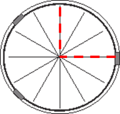
Passive infrared sensor detects movement better when they cut across radial lines.
- Identify pathways that lead into the lighted area, e.g. doors, corridors
- Position the sensor such that the walk-path cuts across radial lines, not towards the sensor
Occupancy sensor detects smaller movement better when the object is closer.
- Identify seating location where people may be stationary for some time
- Position the sensor nearer to the seating area so it could detect smaller body movement
Ultrasonic sensor detects movement better when faced directly.
- Point the ultrasonic transceivers to the area where occupants are likely to be present, e.g. seating area, work cubicle
- Ultrasonic sensing area is shaped like a bell. The area facing sideway of the transceiver is less sensitive. It could be positioned to avoid interference from air-vents
Do not install occupancy sensors near an air-vent
to avoid false triggering
- Allow at least 1m distance between the occupancy sensor and the outlet of a ceiling based vertical air vent
- Allow at least 2m distance between the occupancy sensor and the outlet of a floor based vertical air vent
- Allow at least 2.5m distance between the occupancy sensor and the outlet of a horizontal air vent
Minimize "looking outside" of the door way to prevent movement in the corridor from activating light in a room
- Position the occupancy sensor to minimize the angle of detection facing the doorway.
- Reduce PIR and/or ultrasonic detection range and sensitivity. This can be adjusted on the occupancy sensor.
Conduct pre-installation walk-test to verify suitability of the location occupancy sensor is installed.
- Pre-installation walk-test is recommended to avoid the costly wiring changes after an occupancy sensor is installed
- SUREN occupancy sensors are available in 2 versions: AC powered and DC powered
- DC powered occupancy sensors operate at 24V could be powered by 2 small A23 12V batteries connected in series
- Where AC powered occupancy sensors were selected for the implementation, obtaining a small number of equivalent DC version would prove useful. See table 3 below for equivalent DC powered occupancy sensors
- Before mounting the DC powered occupancy sensor for pre-installation walk test, review the default settings in the occupancy sensor and adjust if necessary
- Place the DC powered occupancy sensor into position using double sided removable adhesive or an 8mm cable tie
- Conduct walk-test. Observe the LED indicator to identify motion detection by the occupancy sensor
- Verify operational comfort. Check against blind spot and false triggering
| AC Powered Occupancy Sensor Model No. |
CL1306 |
CP1308 |
CPL1312 |
CDL1608 |
CDP1808 |
HB1316 |
| Equivalent DC Powered Occupancy Sensor Model No. |
CL306C24 |
CP308C24 |
CPL312C24 |
CDL608C24 |
CDP608C24 |
HB316C24 |
Table 3. Equivalent DC Powered Occupancy Sensors
Installation Manual
Printed copy of the installation manuals is included in the product package. A copy of the installation manual in PDF format is also available in the product section of this website.
Retro-Fitting Occupancy Sensor With A Lighting Circuit
SUREN's occupancy sensors can be installed over a lighting circuit as you will see below. While the switch turns the light on/off, the occupancy sensor turns the light off when presence is no longer detected.
Figure 1 shows an installation of AC powered occupancy sensor over an existing lighting circuit. In this diagram, the live wire (shown in red) from the power supply to the light is routed via an occupancy sensor.
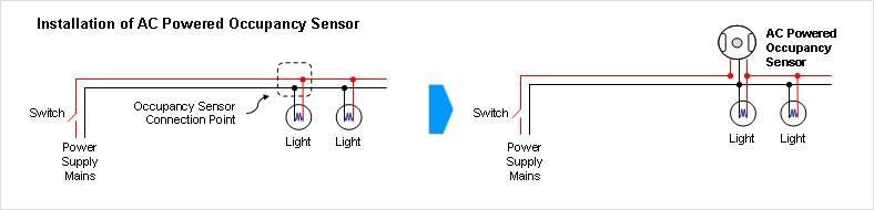
Figure 1. AC Powered Occupancy Sensor Wiring Diagram
When the switch is closed, the relay in the occupancy sensor will turn on the light when presence is detected. The relay will turn off the light when presence is no longer detected. When the switch is open, the occupancy sensor and lighting will be turned off.
Figure 2 shows an installation of a DC powered occupancy sensor over an existing lighting circuit. In this diagram, the live wire (shown in red) from the power supply to the light is routed via a power pack.
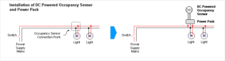 Figure 2. DC Powered Occupancy Sensor Wiring Diagram
When the switch is closed, the occupancy sensor drives a relay in the power pack that turns on the light when presence is detected. The occupancy sensor will drive the relay in the power pack that turns off the light when presence is no longer detected. When the switch is open, the occupancy sensor, power pack and lighting will be turned off.
Handling And Care
Figure 2. DC Powered Occupancy Sensor Wiring Diagram
When the switch is closed, the occupancy sensor drives a relay in the power pack that turns on the light when presence is detected. The occupancy sensor will drive the relay in the power pack that turns off the light when presence is no longer detected. When the switch is open, the occupancy sensor, power pack and lighting will be turned off.
Handling And Care
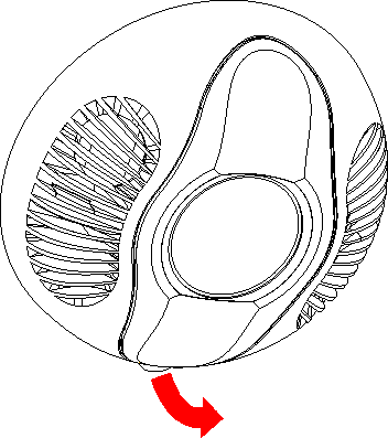
Figure 3 shows the detection components and controls of a passive infrared (PIR) and ultrasonic occupancy sensor. A cover protects the detection components and controls. While the cover is removed to change the settings, it is important to keep the sensor clean.
Avoid touching the PIR and photoelectric sensors to prevent grease and dirt from accumulating. Clean with isopropyl alcohol if needed.
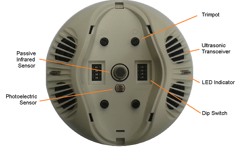
Figure 3. Occupancy Sensor Detection Components and Controls
Sunset Sensor Setting
The sunset sensor saves energy by not switching the lights on when there is sufficient daylight in the room. It can be enabled or disabled by a dip switch on the occupancy sensor. When the sunset sensor is enabled, it goes into stand-by mode when the natural light level exceeds the selected Lux level inhibiting the lights from turning on. Guidance on setting the Lux level on the occupancy sensor can be found in table 4 below.
| Type of Area |
Characteristics of Activity |
Minimum Lux Setting |
| Corridors, walkways |
Interiors rarely visited with visual tasks limited to movement and orientation |
40 |
| Restrooms, loading bays, indoor car parks |
Interiors requiring intermittent use with visual tasks limited to movement, orientation and coarse detail |
80 |
| Waiting rooms, staff canteens, entrance halls, storage rooms, warehouses |
Any continously occupied interior where there are no tasks requiring perception of other than coarse detail. Occasional reading of clearly printed documents for short periods |
160 |
| Classrooms, check-out counters, kitchens |
Continuously occupied interiors with moderately easy visual tasks with high contrasts or large detail |
240 |
| Office |
Areas where visual tasks are moderately difficult with moderate detail or with low contrast |
320 |
Table 4. Minimum Light Level Setting In Australia According
to AS/NZS1680 Standard
Disabling the sunset sensor will turn the lights on whenever presence is detected regardless of the natural light level. This may be necessary where the required light level is higher than the maximum setting provided by the sunset sensor.
When a person enters a room, the occupancy sensor detects movement and turns the lights on. When motion is no longer detected, the occupancy sensor turns the lights off after a set time delay known as the Delayed-Off Time. Delayed-Off Time links discrete/non-continuous movement detected by the occupancy sensor to keep the lights on continuously when people are present.
As you can see in figure 4 below, the Delayed-Off Time enable lights to stay on despite absence of motion detected.
.png)
Figure 4. Delayed-Off Time Scenario
The concept of Delayed-Off Time is further illustrated by the events as follows:
- Lights turn on when a person enters a room
- Lights stay on for the Delayed-Off Time duration when no motion is detected
- Lights stay on if motion is detected before the Delayed-Off Time expires
- Lights stay on for the Delayed-Off Time duration after last person leaves the room
- Lights turn off after no motion is detected and the Delayed-Off Time expires
The Delayed-Off Time is adjustable. A longer Delayed-Off Time wastes more energy as lights stay on longer after the last person leaves the room. A shorter Delayed-Off Time causes lights to turn off more often even when there are people in the room as shown in figure 5.
.png)
Figure 5. Delayed-Off Time Scenario
A shorter Delayed-Off Time causes lights to turn off even when there are people in the room is illustrated as follows:
- Lights turn on when a person enters a room
- Lights turn off when the Delayed-Off Time expires and no motion is detected. At this time, there may be people in the room
- Lights turn on when motion is detected
- Lights turn off after the last person leaves the room and the Delayed-Off Time expires
Setting the Delayed-Off Time duration is dependent upon the ability of the occupancy sensor in detecting presence as shown in figure 6 below.
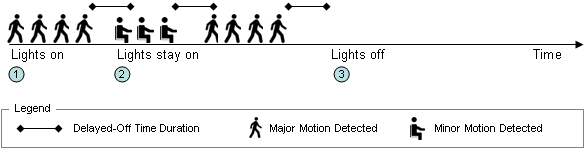
Figure 6. Delayed-Off Time Scenario
A high definition infrared (HDIR) or an ultrasonic sensor capable of detecting smaller body movement will be able to keep the light on with shorter Delayed-Off Time is illustrated as follows:
- Lights turn on when a person enters a room
- Lights stay on before the Delayed-Off Time expired as smaller body movement is detected
- Lights stay on for the Delayed-Off Time duration after last person leaves the room
Generally, walkways and corridors require shorter Delayed-Off Time while offices require longer Delayed-Off Time to keep the light on when people are around.
Guideline on Delayed-Off Time settings:
- Areas where people are moving most of the time, e.g. corridors, walkways : 2 to 3 minutes
- Areas where people may be stationary for some time, e.g. offices, meeting rooms: 10 to 15 minutes
Walk-Through Mode
The walk-through feature is useful in areas that could be momentarily occupied, e.g. hallways, corridors, staff canteens. When a person pass through the area, the occupancy sensor applies a Delayed-Off Time of 2.5 minutes to ensure lights stay on. Because people may stay in the area longer than 2.5 minutes without moving, e.g. reading a document in the corridor, it may be necessary to extend the Delayed-Off Time so the lights stay on.
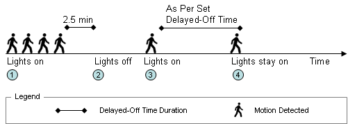
Figure 7. Walk-Through Mode
The method walk-through feature adjusts Delayed-Off Time setting is illustrated as follows:
- Lights turn on when a person enters an area, e.g. hallway, corridor, staff canteen
- Lights turn off when no motion is detected after 2.5 minutes
- If the person is still in the area and attempts to turn on the lights by moving, the occupancy sensor will change the Delayed-Off Time to user-defined setting
- Lights stay on as long as movement is detected within the user-defined Delayed-Off Time setting
If the person is no longer in the area, i.e. no movement detected for more than 10 seconds after light was turned off, the occupancy sensor's Delayed-Off Time will default to 2.5 minutes.
Presentation Mode
The presentation mode is applicable to areas that could be used to conduct presentations with the lights turned off. This feature is delivered by a
multi-function power pack operating with the occupancy sensor and a momentary push-button switch.
In presentation mode, a switch overrides the occupancy sensor and turns off the lights. Lights remain off while presence is detected. If the occupants leave the area while the lights remained off, the occupancy sensor will turn the lights on when presence is next detected. Delayed-Off Time setting is important in this respect to keep the lights off while presentation is in progress.
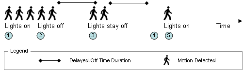
Figure 8. Presentation Mode
Lighting control in presentation mode is further illustrated as follows:
- Lights turn on when people enter a room
- Lights are turned off manually for presentation
- Lights stay off when presence is detected within the Delayed-Off Time
- Presentation mode is cancelled if movement is not detected within the Delayed-Off Time
- Lights turn on when movement is next detected or are switched on manually
Lights can be turned on/off at any time using the switch. If the lights are turned on manually, the occupancy sensor will turn the lights off when motion is no longer detected. If the lights are turned off manually, the multi-function power pack can be configured to either turn on the lights automatically or to have the lights turned on manually.
Passive Infrared Mask
A passive infrared (PIR) mask is provided with the occupancy sensor and may be used to block movement in an area from turning on the light. The PIR mask is installed behind the lens of the occupancy sensor.
To install the PIR mask, open the cover of the occupancy sensor.
Mark and remove sections of the PIR mask where area of detection is required.
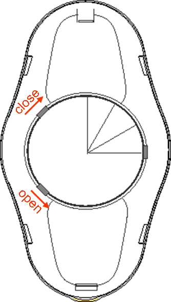
Replace the ring behind the lens of the occupancy sensor with the PIR mask. Turn counter-clockwise to open, clockwise to close.
Conduct walk-test.
Troubleshooting
This section presents possible solutions to issues you may experience after installation.
Issue: Light does not turn on
Probable causes and solutions:
- Loose or incorrect wiring. Review wiring and connections
- Sunset sensor setting is too low inhibiting light from turning on. Increase the sunset sensor setting. Disable the sunset sensor if it is required to set above the adjustable level
Issue: Light does not turn off
Probable causes and solutions:
- Motion detected beyond the intended space, presence of HVAC air-flow or inanimate moving object. Apply PIR mask or relocate the occupancy sensor